Wireshark & Packet Tracer Network Analysis
This case study demonstrates how I investigate networks through simulation, packet inspection, and technical interpretation. It is less about naming tools and more about showing that I can reason through system behaviour with evidence.
Project Story
The value of this project is in connecting theory with observation. It shows how I work through systems by modelling them, inspecting them, and explaining what the evidence means.
Challenge
Understand network behaviour beyond surface configuration and explain how infrastructure choices affect visibility, resilience, and security awareness.
Approach
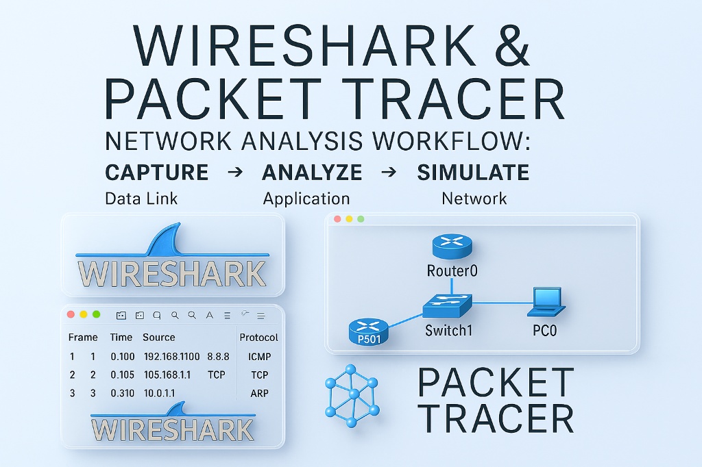
Use Packet Tracer to model architecture and Wireshark to inspect traffic so simulation and live packet evidence support one another.
Outcome
A stronger technical analysis that shows diagnostic thinking, practical tooling ability, and a more credible understanding of how networks behave.
Project Snapshot
This summary block highlights the practical evidence behind the work so the project reads more like demonstrable capability than a tool list.
Diagnostic Toolkit
This visual strip surfaces the working methods behind the analysis so the project feels more grounded in applied technical reasoning.
Use topology simulation to understand structure, flow, and how the network is intended to behave.
Read packet activity to connect architecture decisions with evidence at traffic level.
Turn raw technical observation into clearer conclusions about resilience and visibility.
What This Demonstrates
This project helps turn security interest into something more concrete by showing investigation, interpretation, and technical discipline.
Core Strengths
- Traffic analysis and packet interpretation
- Network modelling and systems thinking
- Diagnostic workflow using real tools
- Security-minded interpretation of behaviour
Why It Matters
For employers, this signals that I can inspect, reason, and explain what is happening inside a system. That is much more useful than simply listing tools on a CV.
Archive Access
The original converted report is still available for anyone who wants the long technical version.
Open the archived report version to review the original Wireshark & Packet Tracer report.